

Arduino UNO + MPU-6050 (GY-521)
I recently purchased a GY-521 sensor which contains a MEMS accelerometer and a MEMS gyro on the same chip. This sensor has a 3-axis Gyroscope and a 3-axis Accelerometer that can measure independently but are based around the same axes. It is a simple module that can be interfaced with the Arduino and other controllers via I2C, providing motion-sensing information for 3 axes (X, Y, and Z). In this project, I will be using the GY-521 with the Arduino Uno to get readings from the sensor to rotate a 3D model of an F-15.
I have to mention that, although I have more than 7 years of experience in building PCs, I am new to Arduino and have limited knowledge of working with electronic parts and microcontrollers. My primary goal is to control the attributes of objects in Maya with the help of an Arduino Uno and some sensors.
Parts required to do this project:
GY-521 Features:
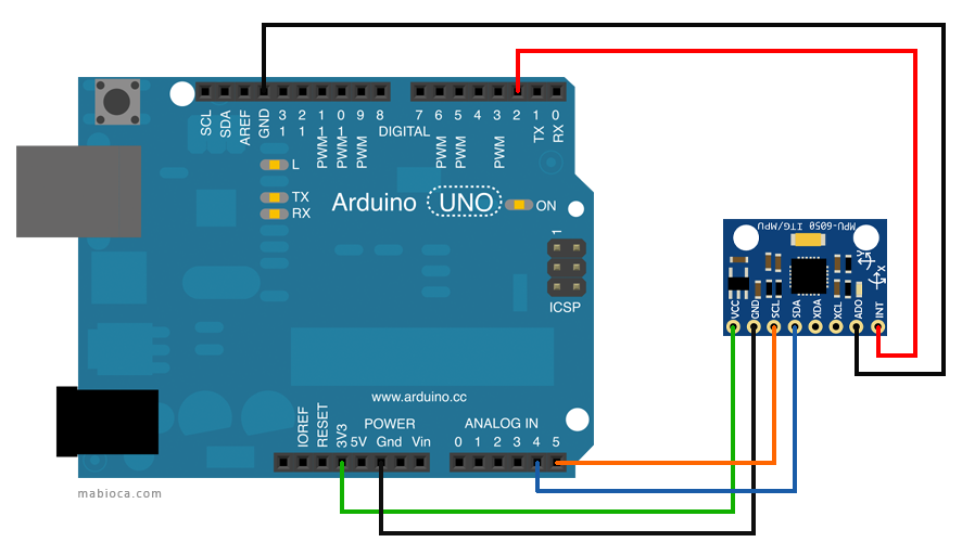
First step: The wiring and connections
| Arduino Uno | GY-521 |
| 3.3V | VCC |
| GND | GND |
| Analog pin 4 | SDA |
| Analog pin 5 | SCL |
| Digital pin 2 | INT |
| GND | ADO |
Note: Only two pins were needed to transmit data on the I2C bus:
SDA (data) <=> Analog pin 4
SCL (clock) <=> Analog pin 5
The MPU-6050 is connected to Arduino as shown in the following diagram:
Second step: I2C Scanner
This sketch scans the I2C bus for devices. If a device is found, it is reported to the Arduino serial monitor, so try to find whether GY-521 is connected to the Arduino. For that, you can use the I2C Scanner version 6 to verify the connected I2C devices to Arduino. Upload the code to Arduino then open the serial monitor and set the data rate in bits per second to 9600 baud for serial data transmission. It should find your GY-521 at the hexadecimal address 0x68. The output below shows the GY-521 is connected with the Arduino.
Scanning…
I2C device found at address 0x68 !
done
The third step is to download and install Jeff Rowberg’s i2cdevlib libraries and see the latest code on github. Go to the root folder and download the zipped files. Unzip the “i2cdevlib-master.zip” file and find the Arduino folder. Copy the “MPU6050” and “I2Cdev” folder to the Arduino “libraries” folder. Arduino stores all the add-on libraries within the “My Documents” folder. Here you see the location of the Arduino “libraries” folder. Libraries will usually contain a .cpp file and a few .h files. Most will also contain an examples folder. To verify the library has been installed correctly, open up the File>Examples folder under the Arduino IDE and you should see “MPU6050_DMP6” and “MPU6050_raw” in the MPU6050>examples folder. Now open up the “MPU6050_DMP6” example and upload it to the Arduino. Open the serial monitor and set the data rate in bits per second to 115200 baud. The output below shows the MPU-6050 is connected successfully.
Initializing DMP…
Initializing I2C devices…
Testing device connections…
MPU6050 connection successful
Send any character to begin DMP programming and demo:
Now you have to do changes in the “MPU6050_DMP” code:
Comment in #define OUTPUT_READABLE_YAWPITCHROLL
Comment out #define OUTPUT_TEAPOT
Upload the modified code to the Arduino and then close the serial monitor.
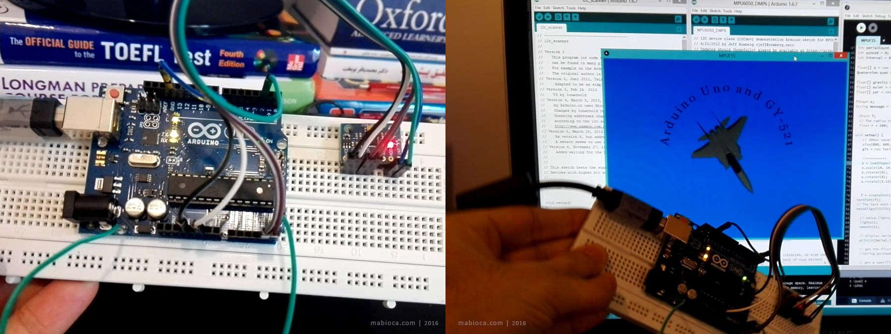
The fourth step is to download and install Processing and toxiclibs libraries and see the latest toxiclibs libraries on bitbucket. Unzip the “toxiclibs-complete-0020.zip” file and copy all folders to the Processing “libraries” in the “My Documents” folder. Download the “F-15 3D Model” and “MPUF15” files from the links below and unzip them in the same folder. Run the Processing IDE and open MPUF15.pde (a modified version of MPUTeapot). Finally, run it by pressing the play button.
Check out this video

Here are some references that I used to learn about the MPU-6050:
Arduino
DIY Hacking
Geek Mom Projects
Dummys Codes
InvenSense
Instructables